![[Virginia Tech Department of Physics]](../images/Mis/vtphyslogo2.gif)
Electricity & Magnetism
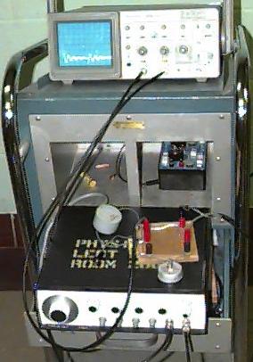
E74: LR and LRC Circuits
![]() Purpose: To see the effects of voltage across the different components in an LRC circuit, and to show transient response in LR circuits and LRC circuits.
Purpose: To see the effects of voltage across the different components in an LRC circuit, and to show transient response in LR circuits and LRC circuits.
|
Lecture Demonstrations | |
Electricity & Magnetism |
||
E74: LR and LRC Circuits |
||
|
||
|
To show effects of the voltage across the components of an LRC circuit: The resistor, capacitor, and inductor are connected in series. You put an AC voltage across and observe the voltage across each one. Observe that the voltage across the inductor leads the voltage across R by 90 degrees and the voltage across the capacitor lags the voltage across R by 90 degrees. To show transient responses: For an LRC circuit, put the square-wave generator in series with the resistor, capacitor, and inductor. For LR circuits, bypass the capacitor. Connect Channel 1 of the oscilloscope across the function generator and Channel 2 across the inductor or the resistor. (For the LRC circuit, better results occur if the scope is connected to the "Lo" output.) Use approximately 1000 Hz for the LR circuit and approximately 100 Hz for the LRC circuit. Various transient responses of the instructor's choice can be demonstrated. |
|
| Storage Location: CHEMP 130A |
|
Function generator | E3.4 |
| Ocilloscope | E3.4 | |
| 1-mF capacitor, 100-mH inductor, 5-kΩ variable resistor. | E3.4 |
|
Manual: None | Setup Notes: E74 | PIRA #: |
| Manufacturer(s): VT | Other school's Demonstration web pages |
![]()