|
Borexino Internal Source Insertion
System
|
This page will house various documents, procedures, photographs, etc. that
pertain to the ongoing
design, fabrication, testing, and installation of the internal source insertion
system. This page will obviously
not be updated as regularly as our designs and ideas change, therefore, if you
want the most up-to-date
information please email, or call, Bruce, Matt or myself (Steve).
If you are looking for the justification for internal sources, and the insertion
system to insert them into the detector, I will refer you to
Henning Back's PHD dissertation. Chapters
four and five deal with these issues explicitly.
Below are a few of the many documents produced by VT members throughout the
design, testing, and installation of the system. I will add more of them
as they become available. For any additional information, the author(s) are listed for each document, you may find our contact info on the VT Members page. There are many design decisions that have been made in lab notebooks, chalk boards, personal communications, etc., thus making it impossible to document them all here, if you have any questions, please don't hesitate to contact one of us.
Insertion System Procedures (Steve Hardy, Bruce Vogelaar):
DOC PDF
Appendix A : Camera System Operations Manual (Bruce Vogelaar):
DOC PDF PS
Appendix B : Camera System Hardware (Henning Back):
PDF PS (Subset of Chapter 6 of Henning Back's PhD Dissertation)
Appendix C : Gas Control System Software (Bruce Vogelaar); Coming Soon
Appendix D : Gas Control System Hardware (Steve Hardy): PDF PS Newly Updated (March 2, 2007)
Appendix D' : List of Hardware Components (Steve Hardy): PDF More of an internal document detailing every nut, bolt, washer, etc., for the glovebox system
Reference A : CR4 Filling Stations P&ID: PDF
Reference B : Military Standard 1246: PDF PS
Reference C : Insertion System P&ID: PDF Formatted for A3 Paper
All PDFs In One Zip File: .tgz .zip (Windows)
Schematic of glovebox & gas handling system (Bruce):
PDF
Tech note on sealing options for glovebox (Steve Hardy):
PDF
Tech note on the hardware and electronics for the tether counter (Steve Hardy), electronics have changed significantly, but
basic idea is still the same: PDF
|
CAD Drawings of various components
Click on thumbnail for full size images
CAD drawings created using SolidWorks 2005. Contact Steve
Hardy
if you want the most recent files. |
|
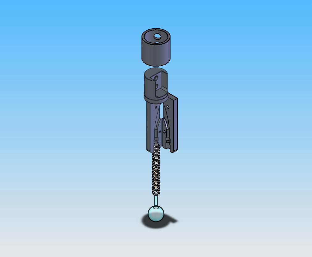
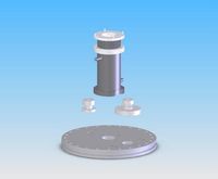
Rod Holder exploded view |
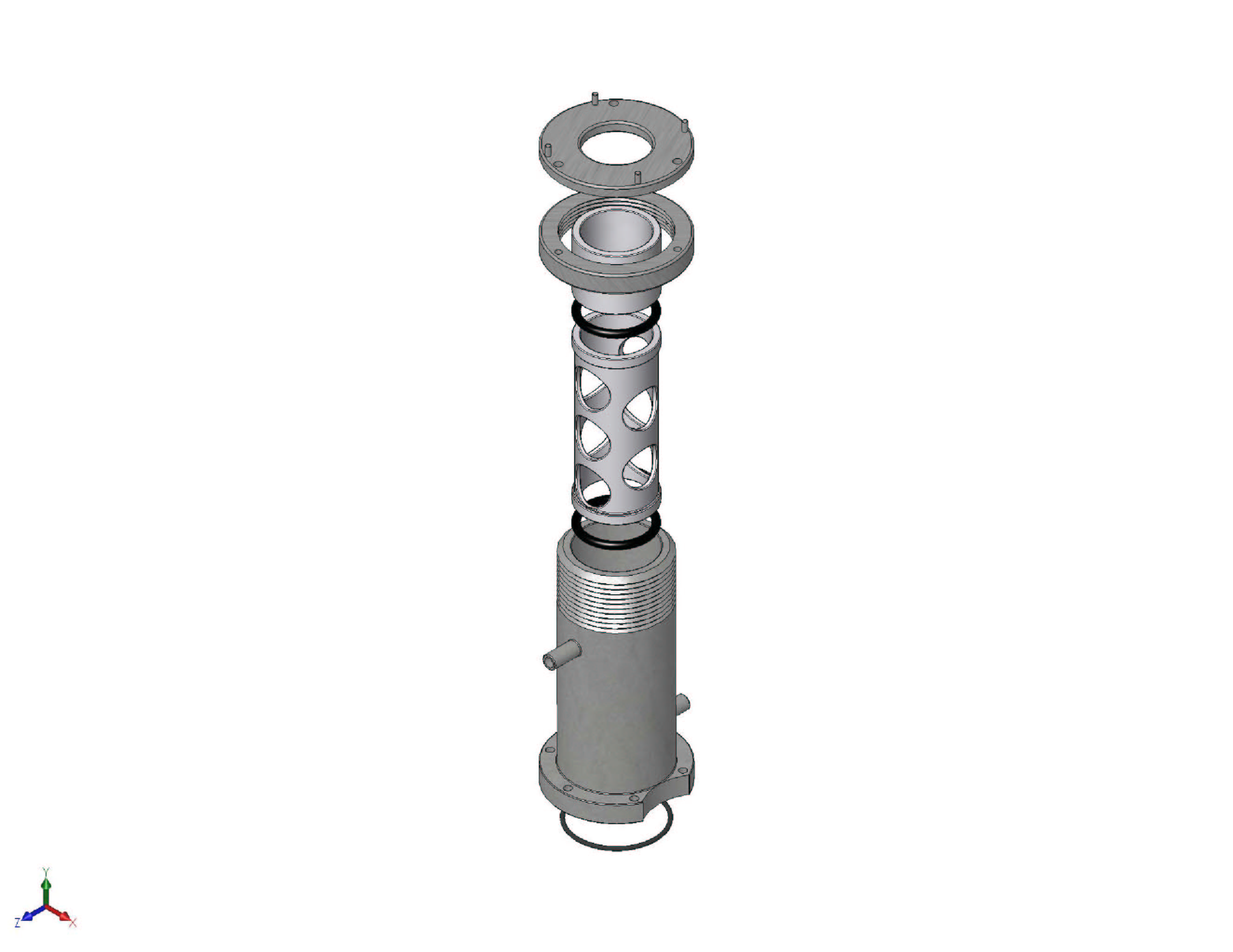
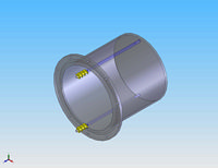
Top feedthru flange exploded |
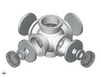
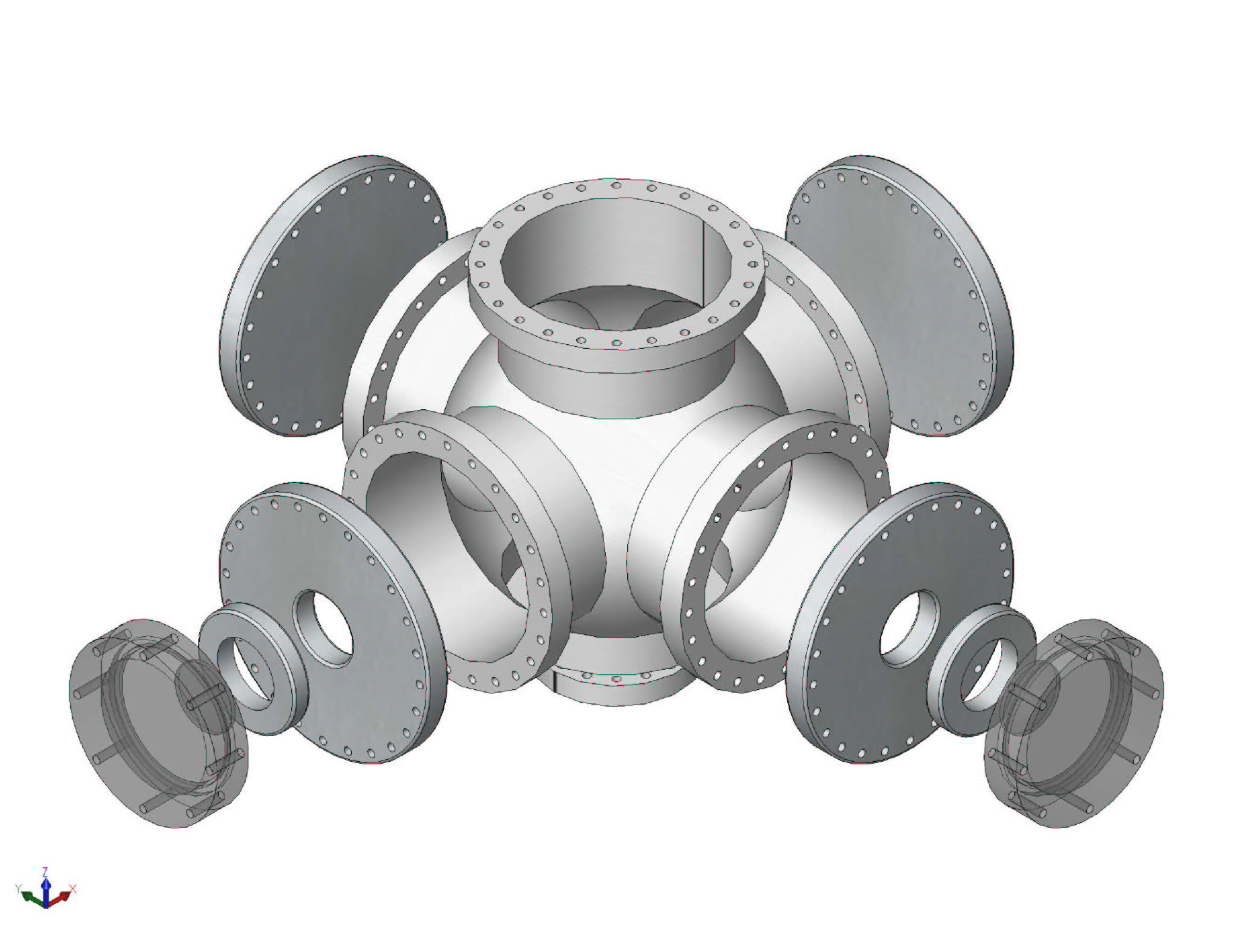
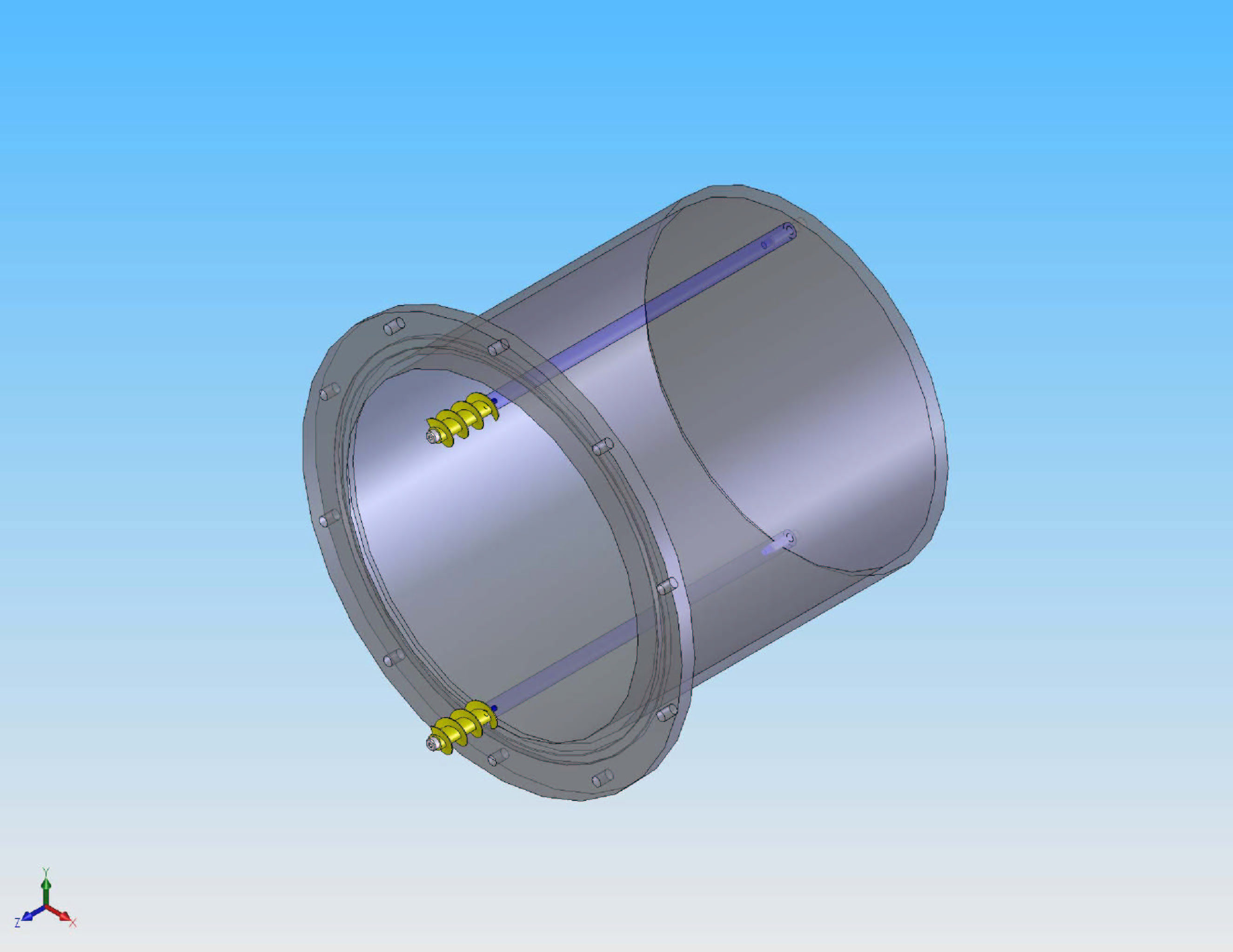
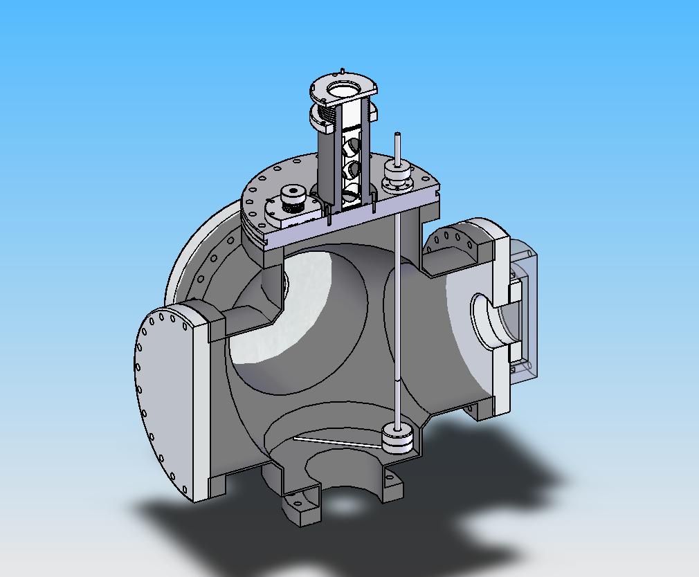
6 way cross exploded |
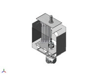
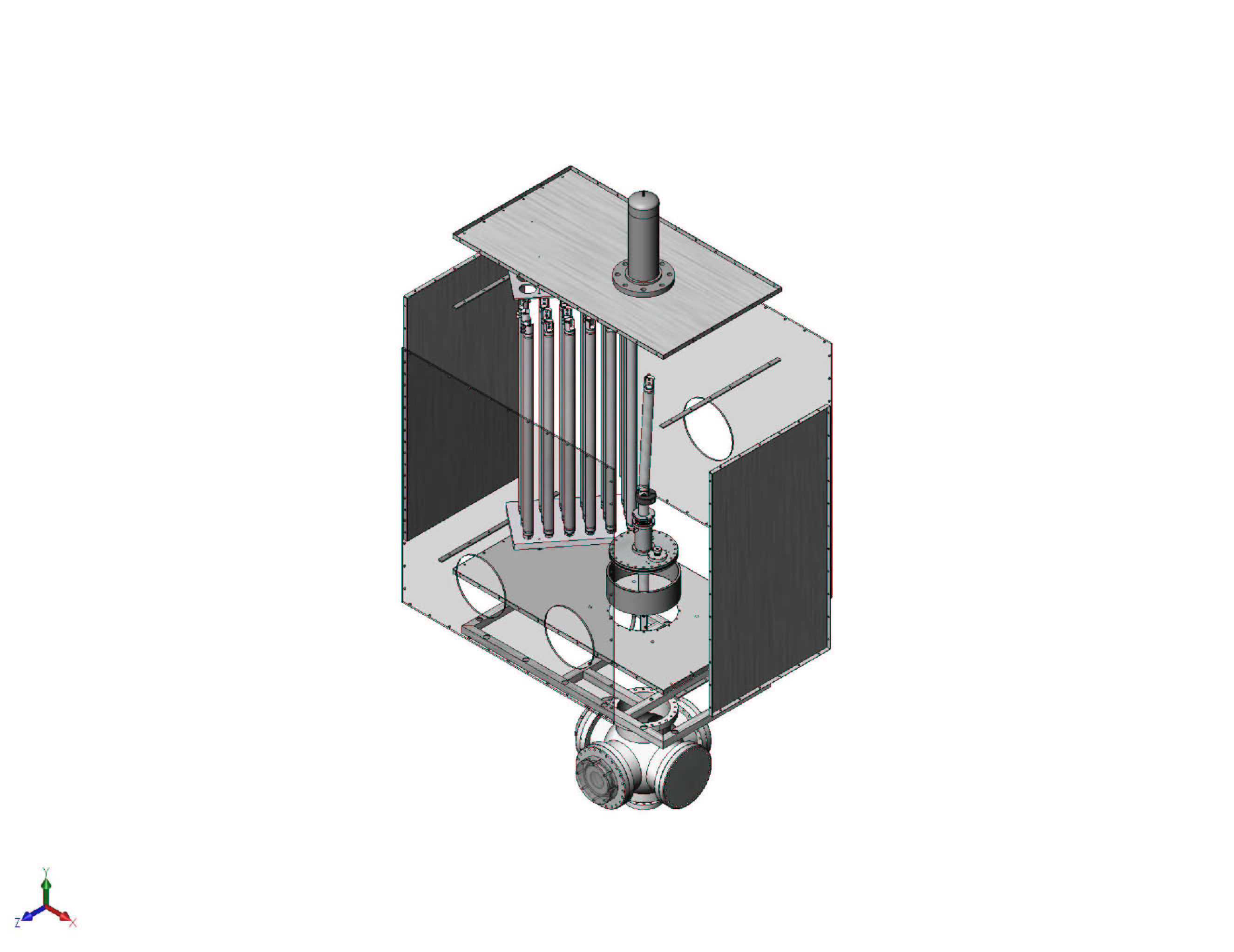
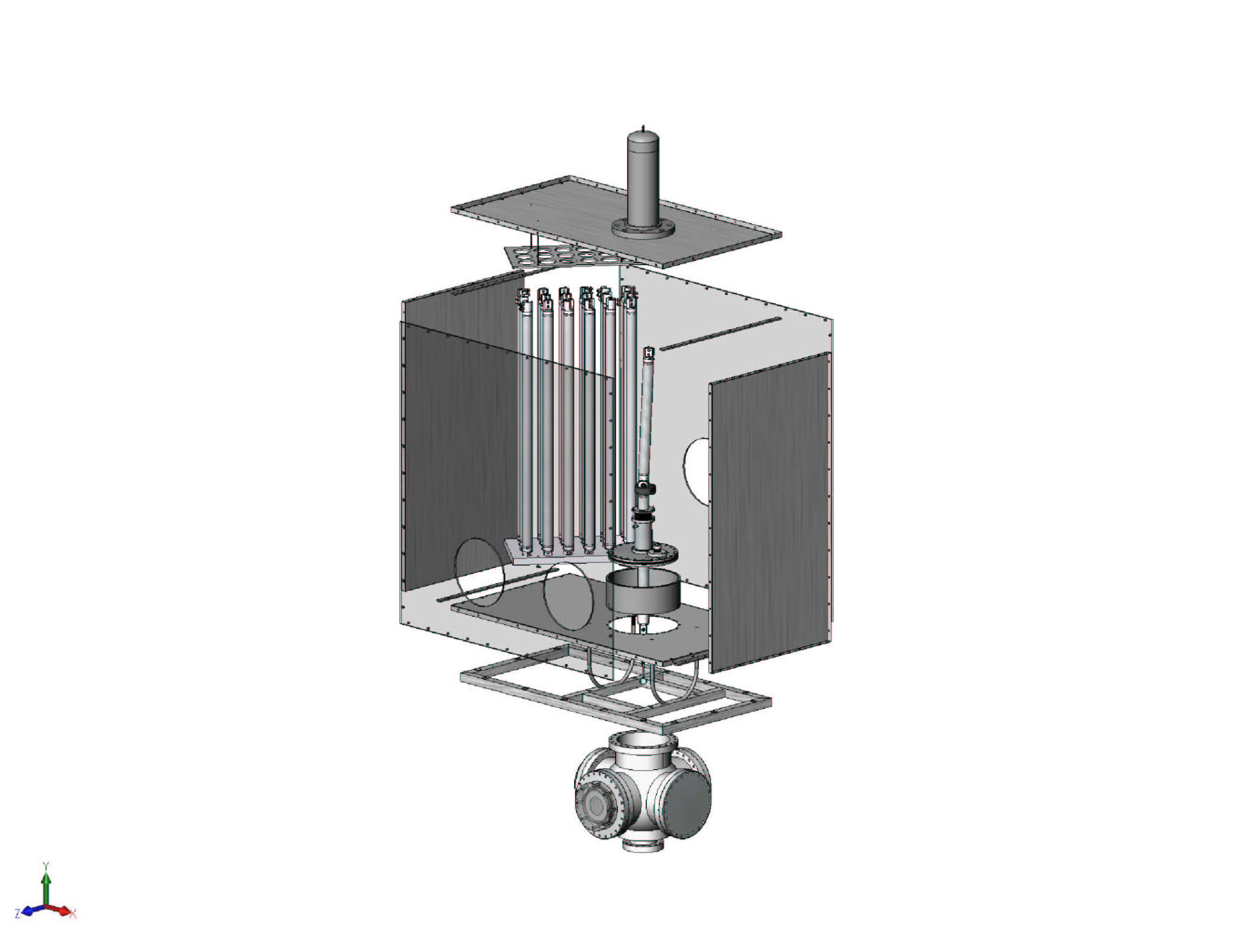
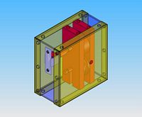
Glovebox exploded (~90% accurate) |
|
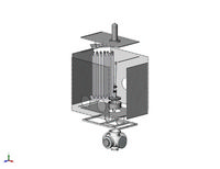
Alternate Glovebox exploded view (~90% accurate) |
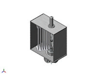
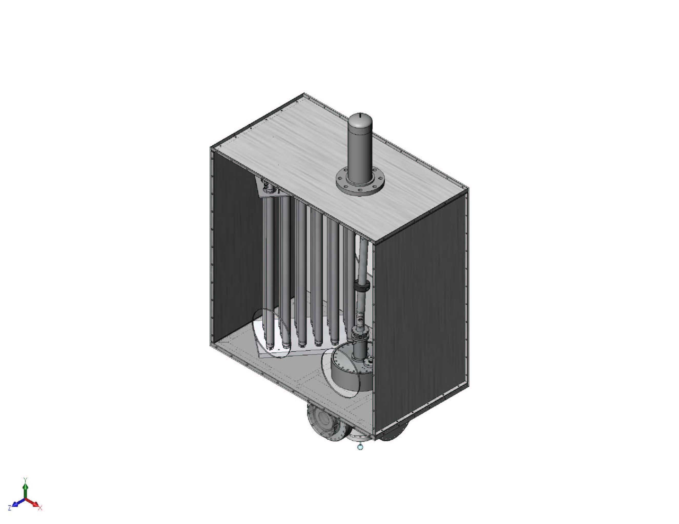
Glovebox Assembly (~90% accurate) |
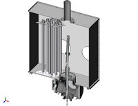
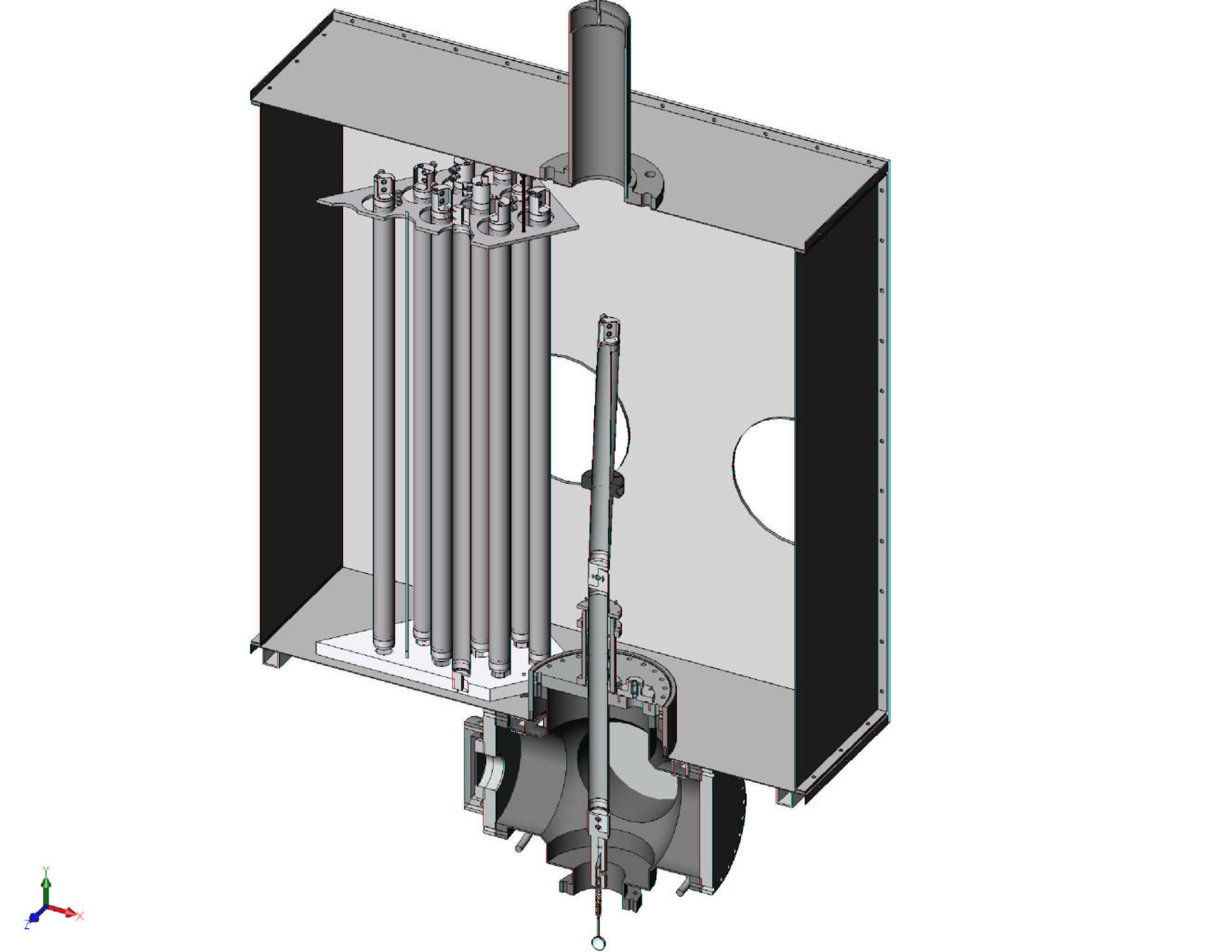
Glovebox section view (~90% accurate) |
Top hat exploded |
|
Rod seal exploded |
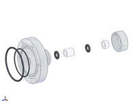
Tube seal exploded |
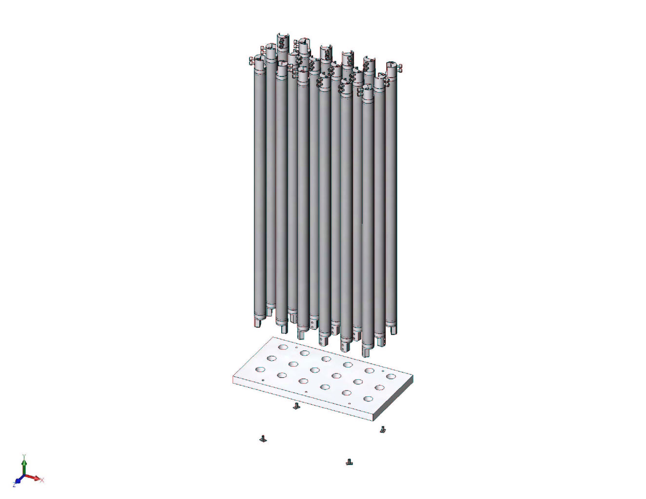
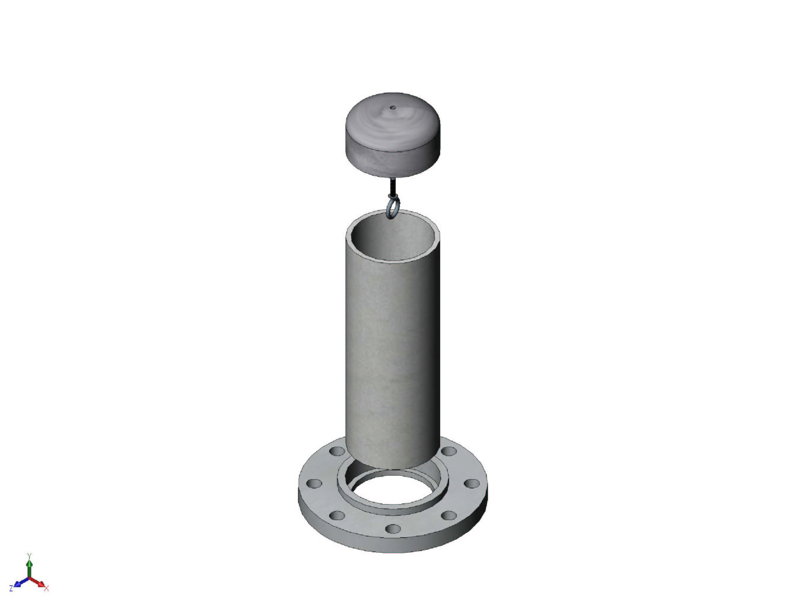
Tether Storage Unit (~90% accurate) |
Tether storage section (~90% accurate) |
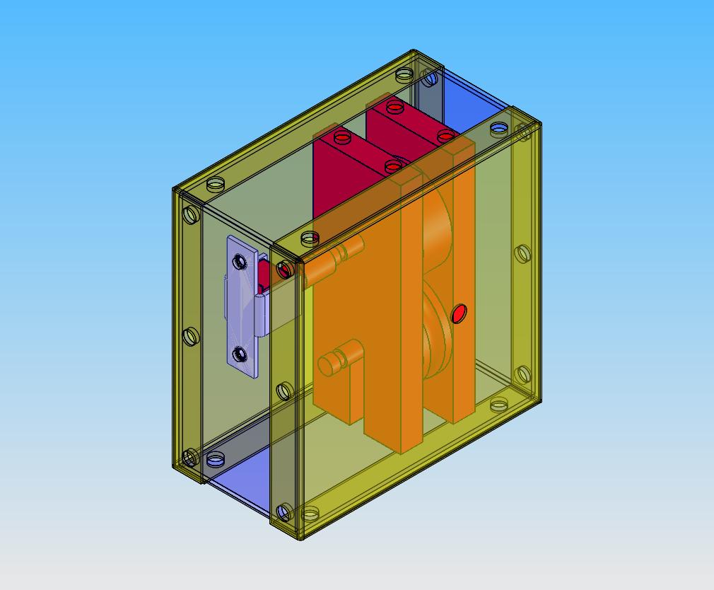
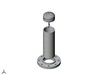
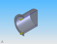
Tether Counter Housing
|

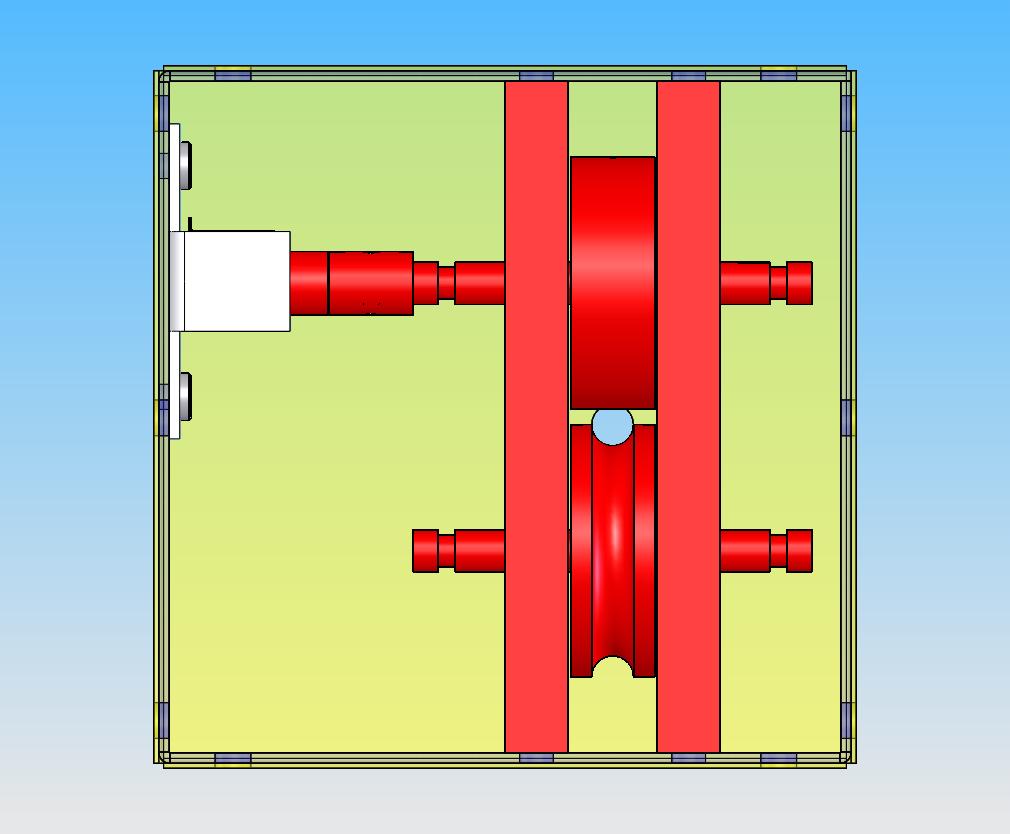
Tether Counter Housing Alternate View
|
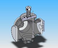
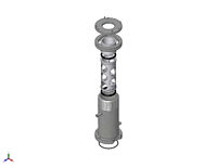
Cross with Liquid Level Monitor
|
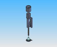
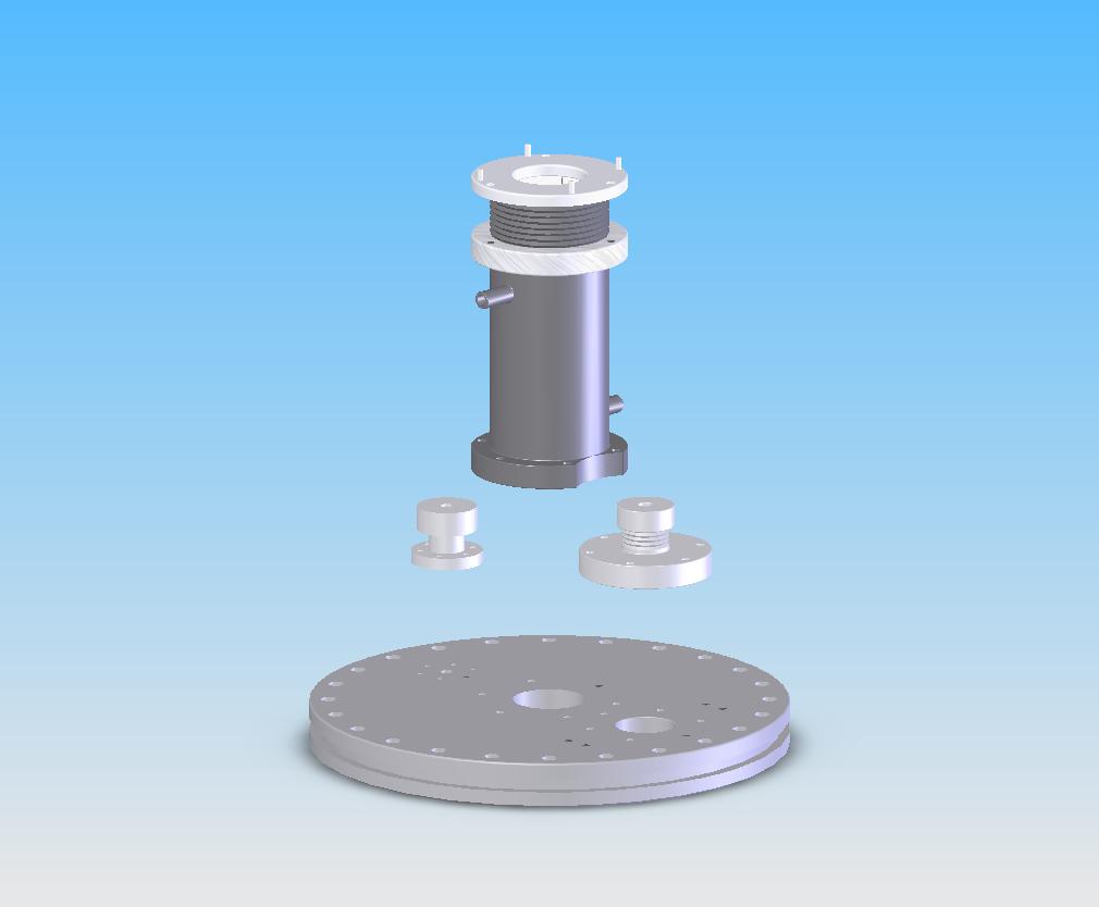
Radioactive Source Coupler
|
Below are photographs of the some of the actual components
during their testing stages. I do not have photographs of many of
them since they are already electropolished and packaged for shipping, but I
will upload pictures once they are unpacked and installed in Gran Sasso.
|
Miscellaneous Hardware Pictures
Click on thumbnails for full size images |
|
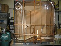
Glovebox panels clamped together
shortly after their fabrication |
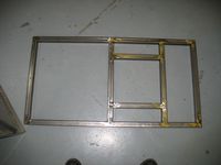
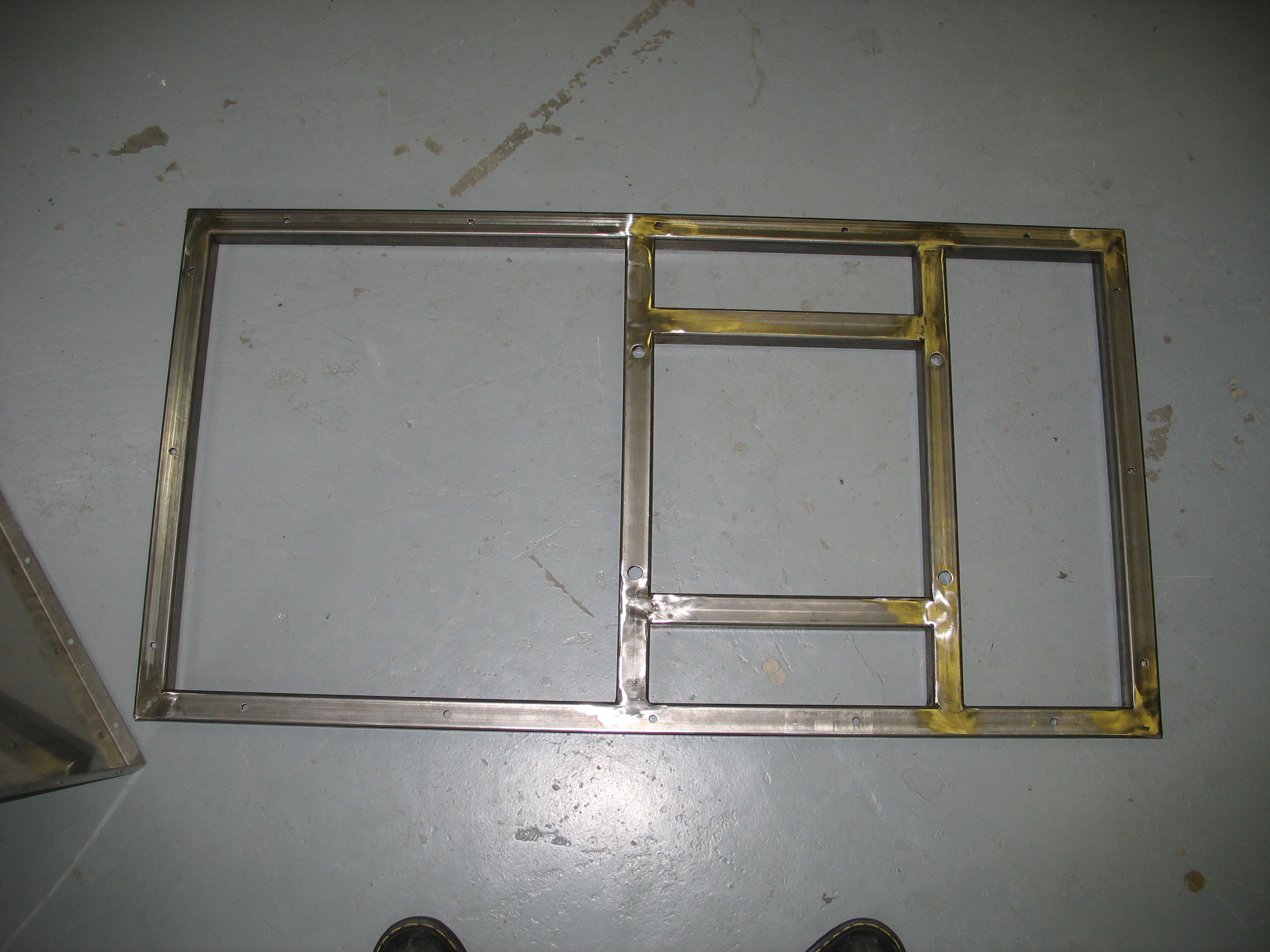
Glovebox support frame to be placed
atop the 6 way cross |
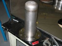
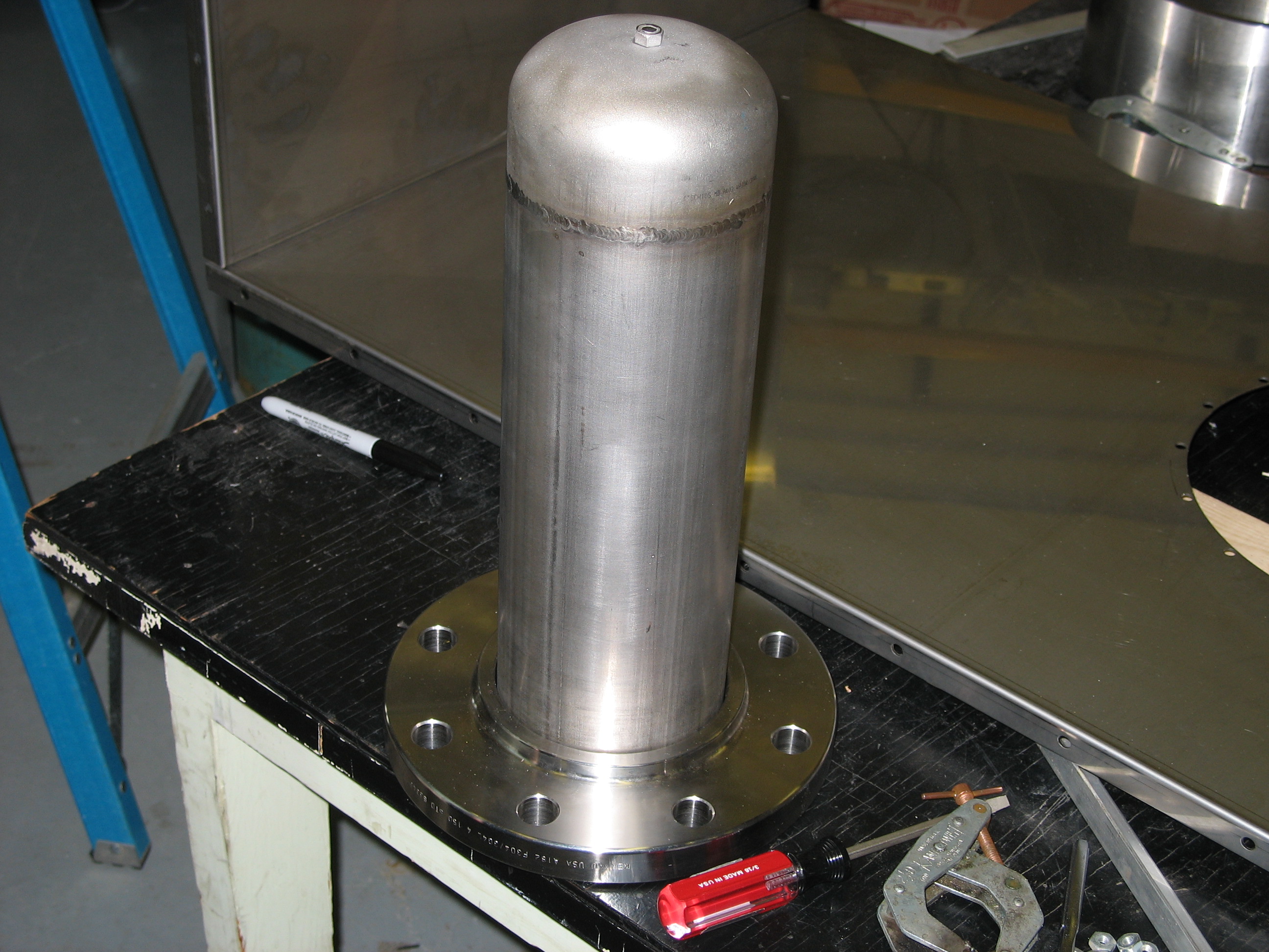
Tophat for glovebox just
after welding |
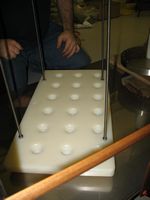
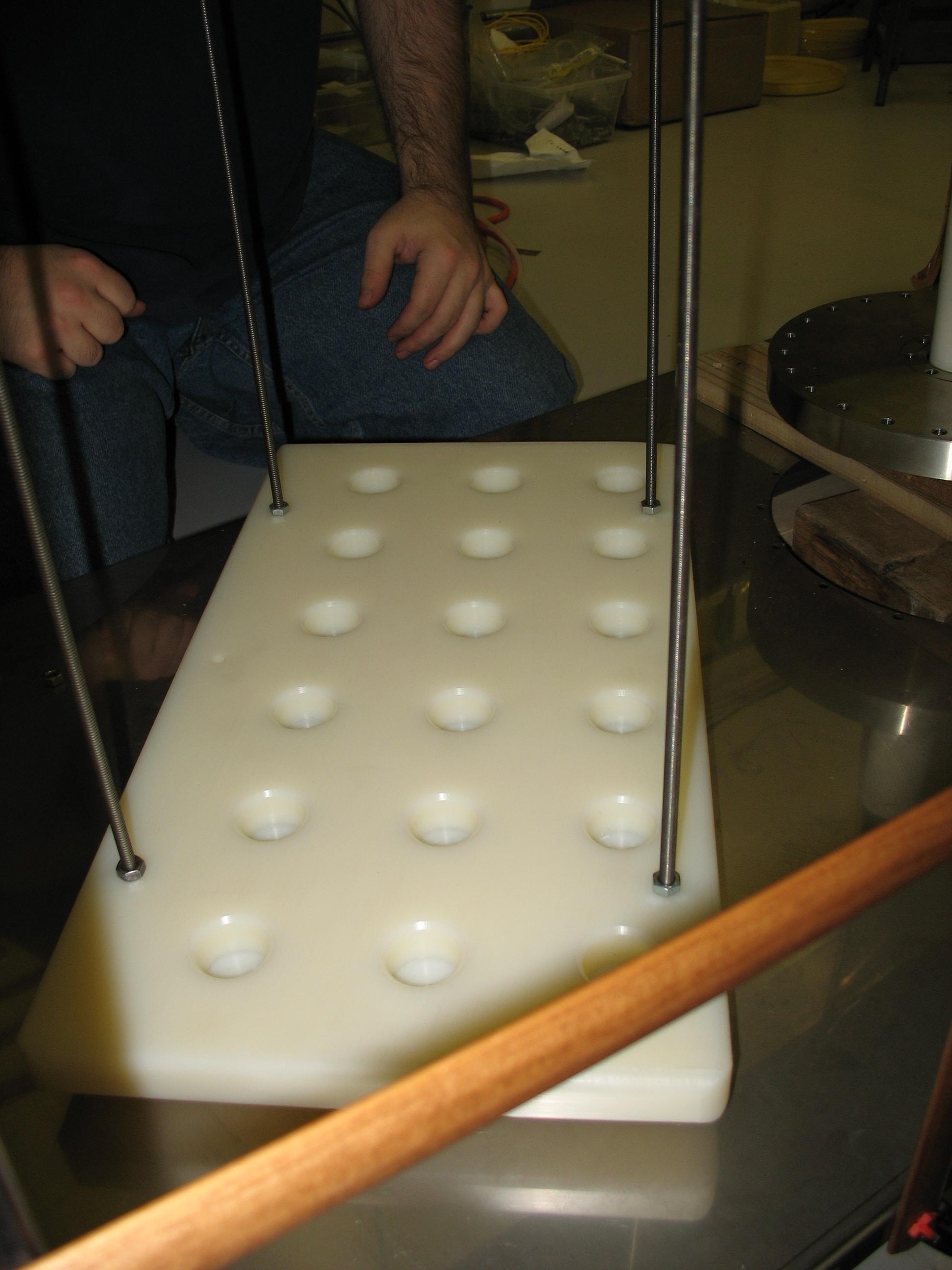
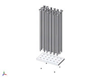
Rod storage base |
|
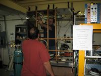
Matt & Athans doing some
assembly work |
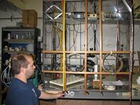
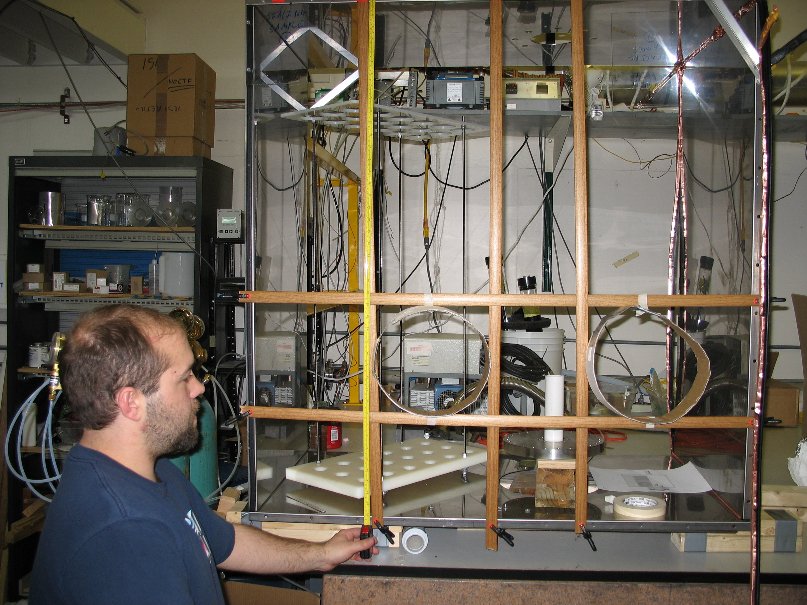
Matt taking some measurements |
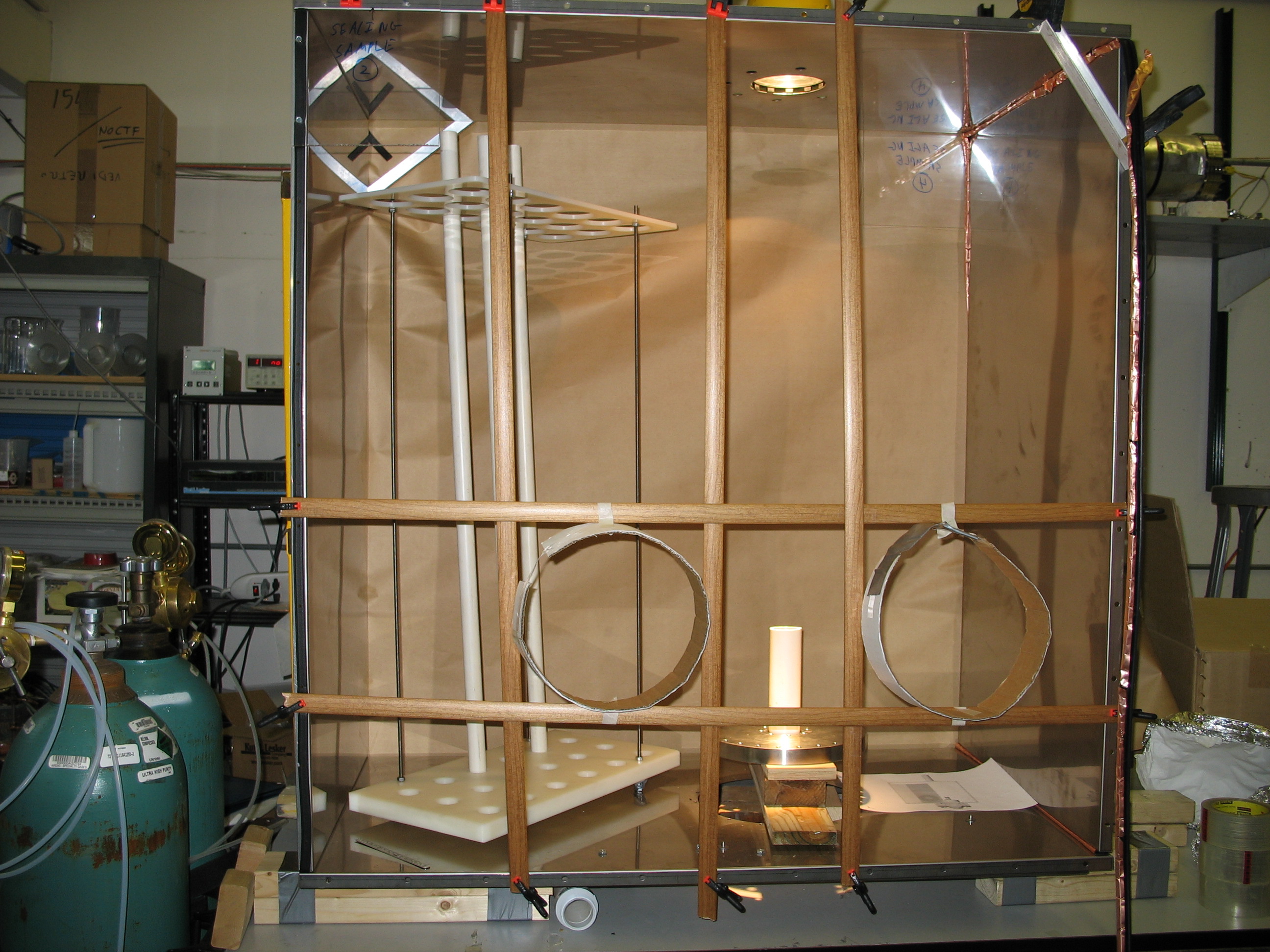
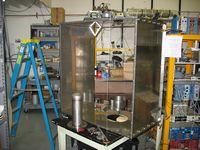
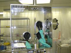
Glovebox during tests for optimum
glove positions. |
Glovebox assembly in progress in the HdM CR |
|
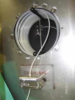
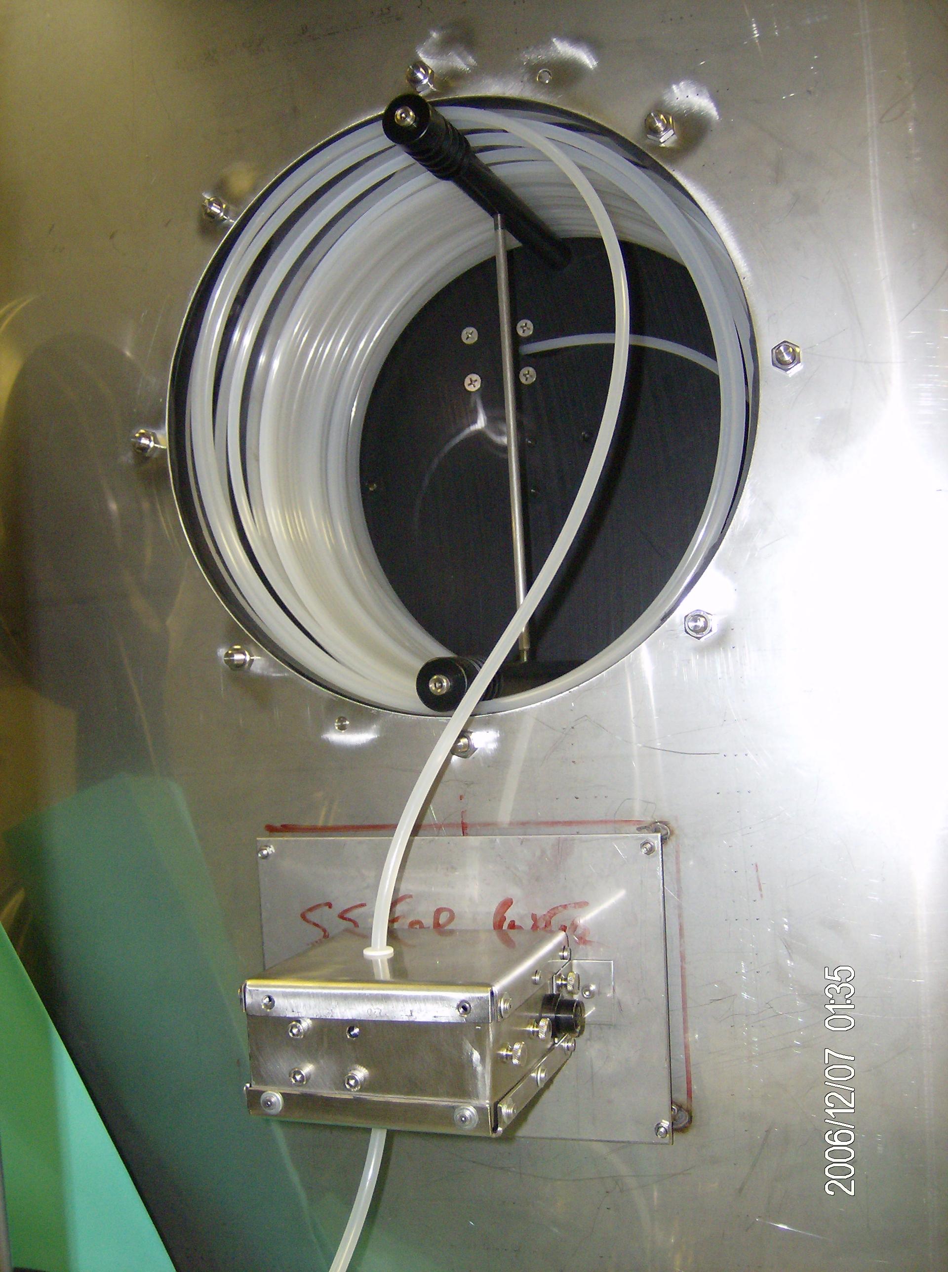
Tether drum and tether counter installed in HdM CR |
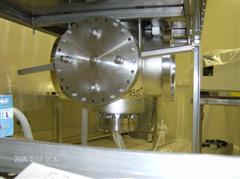
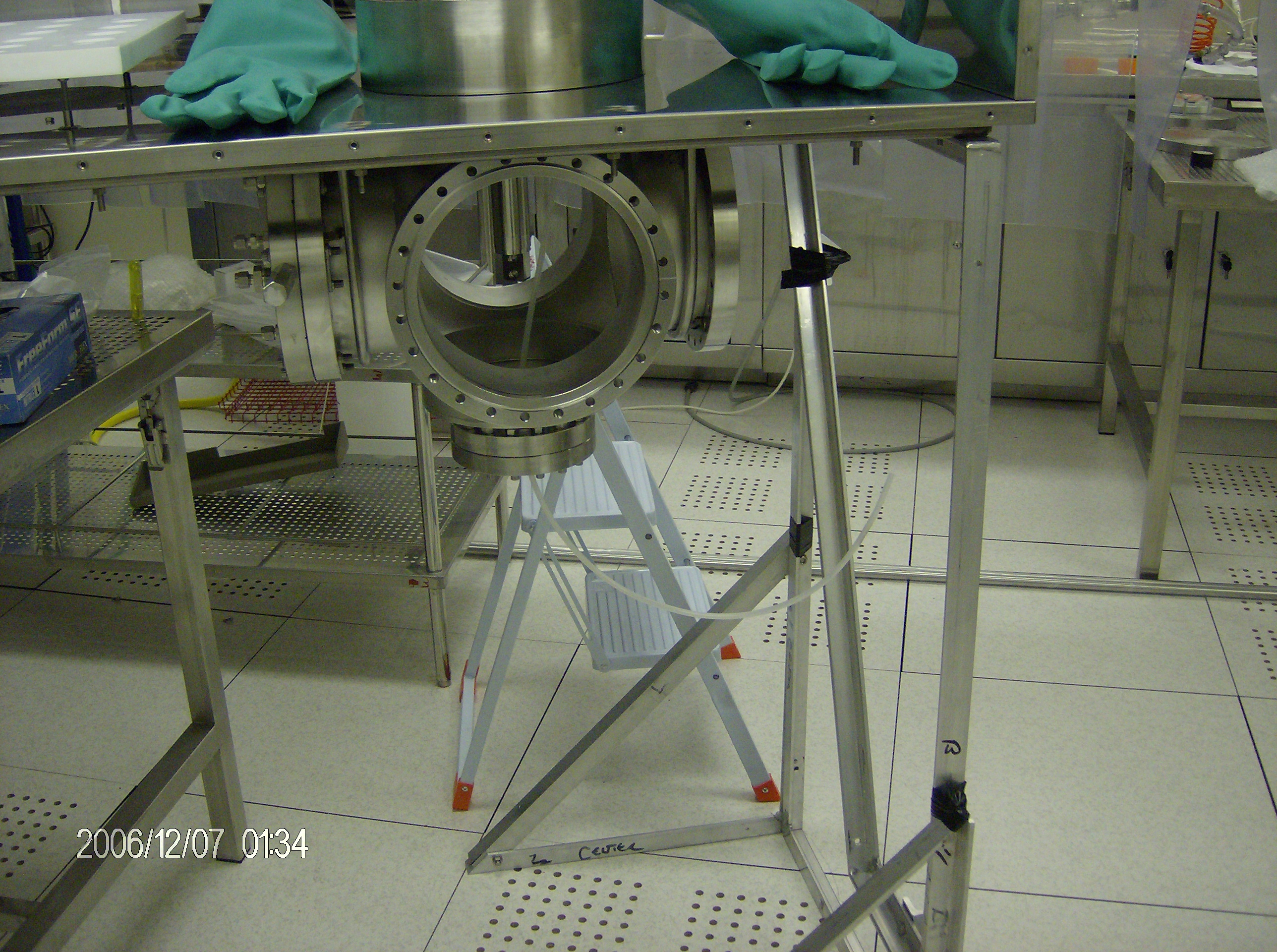
6 way cross installed in HdM CR |
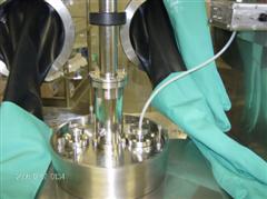
Top flange installed in HdM CR |
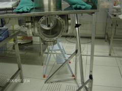
Cross and temporary mounting in HdM CR
Note the insertion rod and tether tube inside of the cross |
Last Updated : December 6, 2006
Webmaster: Steve Hardy